
How to detect a gate's gearmotor open/closed state using 24 V AC/DC accessories power-supply output with a microcontroller?
Most of the gate gearmotor has 24 V AC/DC accessories power-supply output. Useful to connect signaling devices (an external lamp) which is turned on while the gate is open. I wanted to use that information to be able to know if the gate is open or closed in my home automation system. I could use reed switches as I do for the garage door opener. But the priority was to pack everything inside the gearmotor cover because it is on the outside. I wanted to use ESP32/8266 microcontroller, the main problem for me to solve was, how to convert 24 V AC/DC voltage to something that I can connect to GPIO pin, which in the case of ESP can be 0 - 3.3 V.
Optocouplers
I knew that optocouplers can be useful for this, but I wasn't sure how to properly make a circuit that would be false-positive protected. Fortunately, I have found an outstanding article that explains in detail exactly what I needed. I just had to adjust a bit the elements for the 24 V instead of 120/230 V. My gate gearmotor has 24 AC Voltage but the circuit should work also for the DC case. The secondary side of the optocoupler is galvanically separated from mains electricity (inside the optocoupler is LED diode). The diode lights up when the input voltage exceeds around 1.4 V (I used LTV-814/PC817). When the diode lights up the built-in transistor works in the active region and acts as a short circuit. When the output voltage is below 1.4 V (when the gate is closed we expect the voltage to be 0) the transistor operates in the cutoff region and acts as an open circuit. This way we get a relay behavior that can safely connect almost any microcontroller to the output.
I specifically picked the LTV-814 bidirectional optocoupler. It has two LEDs conducting in opposite directions. It simplifies the circuit a bit because thanks to the second LED the effect on the secondary side voltage (AC) will be very similar to the use of a rectifier. The last optional thing but very useful is to add a capacitor between the Emitter and GND. It smooths out the flow which helps to protect from getting too much noise information especially when the input is switching between the 0 - 24 V. The circuit that I picked from the mentioned article:
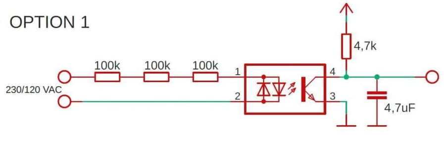
I just changed the resistors from 100k to 2k. Instead of using 1 resistor that could have 6k its a good idea to use a couple of resistors in series as mentioned in the article. > In this way, the power is distributed over several components instead of one. Secondly, and even more important is the maximum voltage that the resistor can take. We have done the detecting part of the AC/DC voltage from the gate gearmotor.
Connecting the voltage detector
Having the voltage detector, I had to connect it between the gearmotor's terminals for signaling devices and the microcontroller's GPIO. I have the CAME BXV series SDNX gearmotor. Using the manual I just had to find where are the connectors for the signaling devices. In my case, it was very easy to access, just unscrue one scrue to take off the cover, and then already on the board ⑫ the terminals ⑱ are visible. Because in my case the ESP8266 will be placed under the gearmotor cover I also could easily add another feature. Using the relay controller by the microcontroller I can short circuit for a short time that is connected to the command terminals ⓸. I already used those to be able open/close my gate from home, by using the wall-mounted momentary-action switch.
| Gearmotor | Board |
|---|---|
 |  |
The whole circuit: 
I placed everything inside a box and it fits nicely inside the gearmotor cover:
| Elements | Placement |
|---|---|
 |  |
Programming
Having that done, the last piece was to program the ESP8266. I used ESPHome. Basically, we have to react to the voltage detection that gives us information if the gate is open or closed (and also when the state is changing). In addition, we can open/close the gate by using the relay. There is one caveat though. We do not if the gate is fully open, and we do not know if the opening ended. At least, I couldn't find in my gearmotor easy access to such information. I could add a reed switch to detect the fully opened state, but I decided that this information is not that important for me. Knowing that I do not have precise open position feedback I implemented time-based cover opening/closing as an alternative and optional feature. The fully open state of the cover is thus always an assumed one, the current position is approximated with the time the cover has been moving in a direction.
Please see the component file to check the full component implementation. I won't describe every detail of it. Its the best to check the code itself to grasp how it works. It might be also interesting for you to check out the gate.yaml file to see how to use and set up the component.
The important bit is that you can configure a few parameters used in the gate component:
   # gate
  gate_duration: 19500ms
  gate_duration_int: "19000"

  gate_close_pin: GPIO14
  gate_close_debounce_time: 500ms

  gate_relay_pin: GPIO4
  gate_relay_active_duration: 400ms
gate_durationandgate_duration_int- configures how long it takes to fully open/close the gate. In my case, it is around 19 seconds. To parameters are required because of the ESPHome limitation to pass the integer information to the component.gate_close_pin- configures which GPIO pin will be used to detect the voltage from the gearmotor.gate_close_debounce_time- configures the debounce time that can programmatically protect from false positives while the state of the voltage detection is changing.500msshould be a reasonable default but you can adjust as needed.gate_relay_pin- configures which GPIO pin will take care of sending a signal to the relay to switch it on and off to a short circuit that will open/close the gate.gate_relay_active_duration- configures how long the relay should short circuit to start the close/open action. Probably anything between250 - 500msshould be fine.
I have all of my IoT devices connected to the open-source home automation Home Assistant. Which allows adding many other features. I have configured push notifications to not forget to close the gate if I left it open for too long. Also, the setup is configured with HomeKit, so Hey Siri, close the gate works nicely and my kids have a lot of fun too while we talk to her to do our home automation :).
This is how it works in action. The first video presents the closing of the gate initiated from Home Assistant (time-based percentage position is changing). The second one shows received notifications about the open/close states (the gate was controlled from a remote).
| Home Assistant | Open/Close state |
|---|---|
 |  |